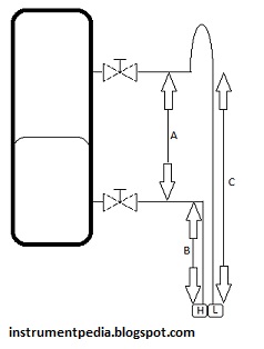
Differential level transmitter for low side dry leg
![level_differential_pressure_transmitter_dry_leg_calibration_installation_commissioning]()
Calibration Procedure:
*Hook up HART Communicator and verify some parameters by refer to data sheet. Typical parameters are, tag number, PV, LRV and URV.
*Isolate the instrument from the process.
*Remove connection at manifold to the process after release the process pressure
*Connect pressure calibrator to high side of manifold
*Expose the low side to atmosphere
*Hook up a multimeter in series with the signal to the DCS to measure current signal.
*Apply pressure as per data sheet LRV
Multimeter should show 4mA
If not, do zero adjustment at transmitter using HART Communicator
*Apply pressure as per data sheet URV
Multimeter should show 20mA
If not, do span adjustment at transmitter using HART Communicator
*Verify the linearity by increasing and decreasing the pressure (0%,25%,50%,75%,100%,75%,50%,25% and 0%of range)
Note
LRV and URV range from data sheet should include the pressure effect from bottom flange height to the transmitter and the SG of process liquid.
Example calculation
S.G=0.89
A= 2000mm (measurement length)
B= 100mm (off set)
C=A+B=2100mm
Dp = pressure at high side – pressure at low side
LRV = (B x S.G) – pressure at low side
= (100mm x 0.89) – 0
= 89 mmH2O
URV = (C x S.G) – pressure at low side
= (2100mm x 0.89) – 0
= 1869 mmH2O
Related posts:
Displacer level transmitter calibration and installation consideration
Capillary type DP level transmitter
Flow transmitter pitot type calculation and calibration
DP Flow transmitter calculation and calibration.